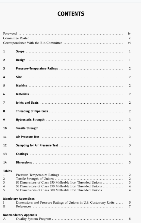
ASME B16.20:2012 pdf download.Metallic Gaskets for Pipe Flanges.
5.2 Dimensions and Tolerances
5.2.1 General. Dimensions and tolerances for gired metal gaskets with covering layers and centering rings shall be in accordance with Fig. 3 and Tables 26 through 211 (Tables 1-15 through 1.17 of Mandatory Appendix I) and as spcthed in this section.
5.2.2 Construction. Grooved metal gaskets with covering byers shall be constructed as a concentrically grooved metal core (scaling element) with a centering ring. The groosed metal portion of thc finished gasket shall be faced with a covering layer on both scaling surfaces that is 0.46-mm (0.018-in.) to0.56-mm (0.022-in.) thick. The thickness of the metal core of the gasket shall be 2.97 mm (0.117 in,) to 3.33 mm (0.131 in.). The thickness on any single gasket shall be uniform within a maximum tolerance range of 0.13 mm (0A)5 in.).
5.2.3 WeldIng. Welding is permitted only in NPS 14 and larger gaskets. Welding shall be subject to the following:
(a) Full penetration welds shall be used.
(b) Where only two welds are used, the minimum weld spacing shall be 152 mm (6 in.). Where more than two welds are required, minimum weld spacing shall be 609 mm (24 in.). Weld spacing shall be measured along the inside circumference of the metal core. When material availability precludes this weld spacing, then additional welding, as agreed by the purchaser and manufacturer, is permitted.
(c) The grooves shall be machined into the core after welding.
(d) In welded areas, the groove, peak profile, and base metal shall be uniform in spacing. thickness, and height with the adjacent metal core.
(e) When specified by the purchaser, weld inspection methods, such as ultrasonic or radiographic, along with acceptance criteria, shall be established.