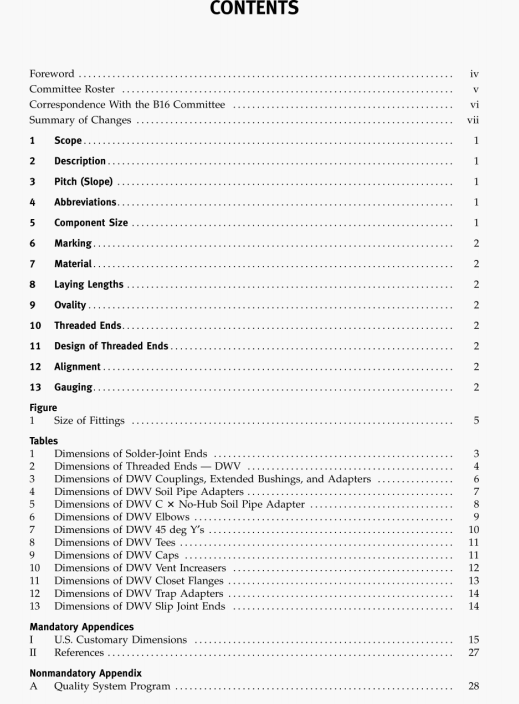
ASME B16.29:2007 pdf download.Wrought Copper and Wrought Copper Alloy Solder-Joint Drainage Fittings - DWV.
10.3 Threading Tolerances
Tapered pipe threads (NPT) shall be checked by use of plug or ring gauges. in either standard or limit types. When gauging internal taper threads, the plug gauge shall be screwed handtight into the fitting. The reference point for gauging internal product threads depends on thedam1er diameter. When the internal chamfer diameter exceeds the major diameter of the internal thread, the reference point shall bc the last thread scratch on thechamfer cone. Otherwise, when the internal chamfer diameter does not exceed the major diameter of the internal thread, the reference point shall be the end of the fitting. In gauging external taper threads, the ring gauge shall be screwed handtight on the internal thread. On the external thread, the ring gauge shall be flush with the end of the thread. Cauging practices shall be as shown in Notes (3) arid (4) of Table 2. Straight pipe threads (NI’SM) shall he checked by the use of standard GO and NOT GO plug and ring gauges.
11 DESIGN OF THREADED ENDS
Ixternal and internal threaded ends of fittings will be furnished with a polygon to facilitate installation.
12 ALIGNMENT
The maximum allowable variation in the angular alignment of all openings shall be 5 mm in I m (0.06 in. in 1 ft) (03%), other than in the direction of pitch (see sectIon 3).
13 GAUGING
13.1 Standard Gauging Method of Solder joint Ends
The standard method of gauging the diameter tolerances for male and female ends shall be by use of plain plug and ring gauges designed to hold the product within the limits established in Table l.
